




How to design a double spur gear for a specific rotational speed?
 Sep 23, 2025|
 Designing a double spur gear for a specific rotational speed requires a comprehensive understanding of gear theory, engineering principles, and the specific requirements of the application. As a double spur gear supplier, I've had the privilege of working on numerous projects where precise rotational speed control was crucial. In this blog post, I'll share my insights on how to design a double spur gear system to achieve a specific rotational speed.
Understanding the Basics of Double Spur Gears
Double spur gears consist of two sets of spur gears mounted on parallel shafts. Spur gears are the simplest type of gear, with teeth that are straight and parallel to the axis of rotation. The primary function of a double spur gear system is to transmit power and motion between two parallel shafts while changing the speed and torque.
The key parameters in gear design include the number of teeth, pitch diameter, module (or diametral pitch), pressure angle, and face width. These parameters determine the gear's size, strength, and the speed ratio between the input and output shafts.
Step 1: Define the Requirements
The first step in designing a double spur gear for a specific rotational speed is to clearly define the requirements of the application. This includes:
- Input and Output Rotational Speeds: Determine the desired rotational speed of the input and output shafts. For example, if the input shaft rotates at 1000 RPM and the output shaft needs to rotate at 500 RPM, the speed ratio is 2:1.
- Torque Requirements: Calculate the torque that the gear system needs to transmit. This is crucial for determining the size and strength of the gears.
- Load Conditions: Consider the type of load (e.g., constant, variable, shock load) and the operating environment (e.g., temperature, humidity, dust).
Step 2: Select the Gear Material
The choice of gear material depends on several factors, including the load requirements, operating conditions, and cost. Common gear materials include steel, cast iron, bronze, and plastic. Steel is the most widely used material due to its high strength, durability, and wear resistance.
When selecting the material, it's important to consider its mechanical properties, such as hardness, toughness, and fatigue strength. Heat treatment can also be used to improve the material's properties and enhance the gear's performance.
Step 3: Determine the Gear Ratio
The gear ratio is the ratio of the number of teeth on the driven gear to the number of teeth on the driving gear. It determines the relationship between the input and output rotational speeds. To achieve a specific rotational speed, you need to calculate the appropriate gear ratio.
The formula for calculating the gear ratio (GR) is:
[GR=\frac{N_d}{N_d}]
where (N_d) is the number of teeth on the driven gear and (N_d) is the number of teeth on the driving gear.
For example, if you want a gear ratio of 2:1 and the driving gear has 20 teeth, the driven gear should have 40 teeth.
Step 4: Calculate the Pitch Diameter
The pitch diameter is the diameter of the imaginary circle that the gear teeth would form if they were extended to a point where they would mesh perfectly with another gear. It is an important parameter in gear design as it determines the size of the gear and the center distance between the shafts.
The formula for calculating the pitch diameter (D) is:
[D = m \times N]
where (m) is the module (or diametral pitch) and (N) is the number of teeth.
The module is a measure of the size of the gear teeth and is defined as the ratio of the pitch diameter to the number of teeth. It is typically expressed in millimeters.
Step 5: Select the Pressure Angle
The pressure angle is the angle between the line of action and the common tangent to the pitch circles of the meshing gears. It affects the force distribution between the gear teeth and the efficiency of the gear system.
Common pressure angles are 14.5°, 20°, and 25°. A larger pressure angle results in a more efficient gear system but also increases the contact stress between the teeth. The choice of pressure angle depends on the application requirements and the load conditions.
Step 6: Determine the Face Width
The face width is the width of the gear teeth along the axis of rotation. It affects the load-carrying capacity of the gear and the amount of contact between the teeth.
A wider face width generally results in a higher load-carrying capacity but also increases the size and weight of the gear. The face width should be selected based on the torque requirements and the allowable contact stress.
Step 7: Check the Gear Strength
Once the gear parameters have been determined, it's important to check the gear strength to ensure that it can withstand the applied loads. This involves calculating the bending stress and contact stress on the gear teeth.
The bending stress is caused by the force applied to the gear teeth as they mesh, while the contact stress is due to the contact between the teeth. There are several standards and formulas available for calculating these stresses, such as the AGMA (American Gear Manufacturers Association) standards.
If the calculated stresses exceed the allowable stresses for the selected material, the gear design may need to be revised by increasing the size of the gear, changing the material, or modifying the tooth profile.
Step 8: Design the Gear Profile
The gear profile is the shape of the gear teeth. The most common gear profile is the involute profile, which has several advantages, including smooth meshing, constant velocity ratio, and ease of manufacturing.
The involute profile is generated by the unwrapping of a taut string from a base circle. The shape of the involute profile is determined by the pressure angle and the number of teeth.
Step 9: Consider Lubrication and Cooling
Proper lubrication is essential for the smooth operation and long life of a double spur gear system. Lubrication reduces friction, wear, and heat generation between the gear teeth.
The type of lubricant used depends on the operating conditions, such as temperature, speed, and load. Common lubricants include mineral oils, synthetic oils, and greases.
In some applications, cooling may also be required to prevent overheating of the gears. This can be achieved through the use of cooling fins, oil coolers, or forced air cooling.
Step 10: Manufacturing and Quality Control
Once the gear design is complete, the gears need to be manufactured to the specified dimensions and tolerances. Common manufacturing processes for spur gears include hobbing, shaping, and milling.
Quality control is crucial to ensure that the gears meet the design requirements. This involves inspecting the gears for dimensional accuracy, surface finish, and material properties. Non-destructive testing methods, such as ultrasonic testing and magnetic particle testing, can also be used to detect any internal defects.
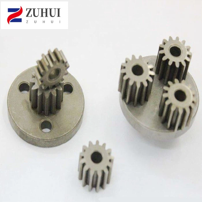

Our Product Offerings
As a double spur gear supplier, we offer a wide range of high-quality double spur gears designed to meet the specific requirements of various applications. In addition to our standard double spur gears, we also provide custom gear solutions tailored to your unique needs.
We also offer related products such as Sintering Planetary Gear, Tiny Small Gear, and Small Metal Gear Sets. These products are manufactured using advanced powder metallurgy techniques, which offer several advantages, including high precision, excellent material properties, and cost-effectiveness.
Contact Us for Procurement
If you're looking for a reliable double spur gear supplier for your project, we'd love to hear from you. Our team of experienced engineers and technicians can work with you to design and manufacture the perfect double spur gear system to meet your specific requirements.
Whether you need a standard gear or a custom solution, we have the expertise and resources to deliver high-quality products on time and within budget. Contact us today to start the procurement process and discuss your gear needs.
References
- Dudley, D. W. (1962). Gear Handbook. McGraw-Hill.
- Mott, R. L. (2004). Machine Elements in Mechanical Design. Pearson Prentice Hall.
- AGMA Standards. American Gear Manufacturers Association.